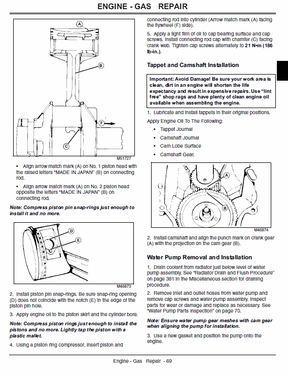
Connecting Rod Alignment Procedure
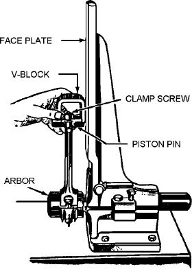
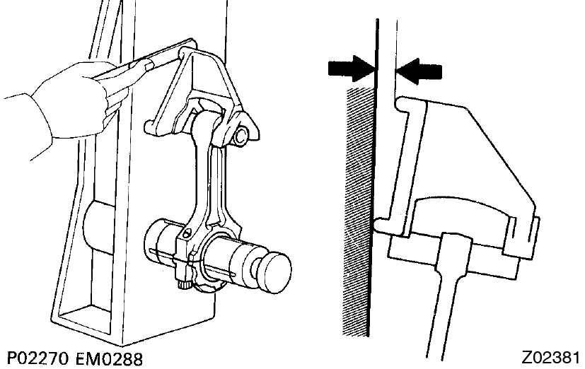
Figure 3 32 Checking Connecting Rod Alignment

How To Blueprint Engines Connecting Rods Guide Muscle Car Diy
Toyota Corolla Repair Manual Overhaul Cylinder Block Assy Emission Control
Automotive Mechanics Connecting Rod Aligner

Connecting Rods Must Be Accurately Aligned Model A Garage Inc
Inspecting Maintaining And Repairing Connecting Rods
Offset designed into a rod places either.
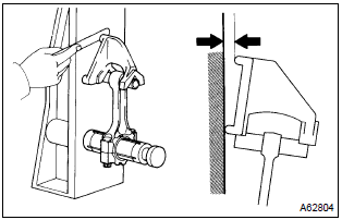
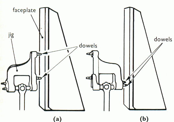
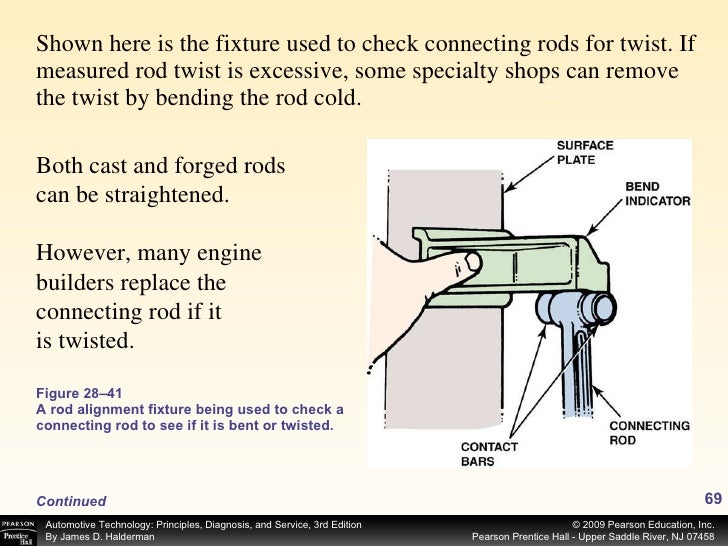
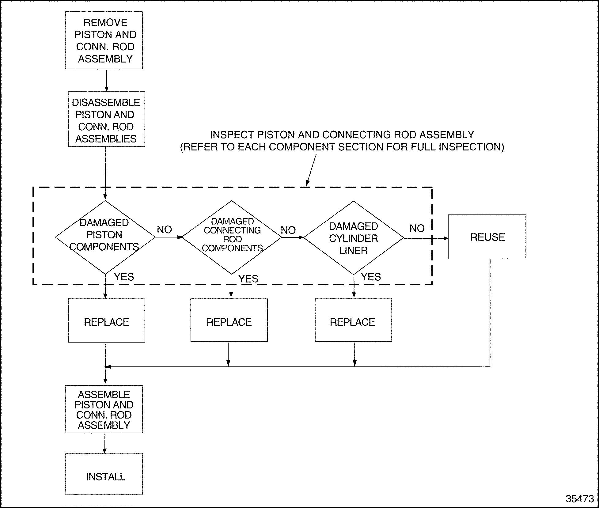
Connecting rod alignment procedure. W cr about x axis 𝜎𝑐 𝐴 1 𝑎 𝐿 𝐾𝑥𝑥 2. The piston pin must be installed in the. The importance of accurately aligning connecting rods cannot be over emphasized. Measure the progress on a rod alignment fixture.
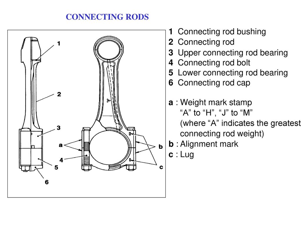
A connecting rod should be equally strong in buckling about either axis. Many pistons are replaced unnecessarily due to out of line rods. D 001 of inter fence. Piston and connecting rod assembly if removed.
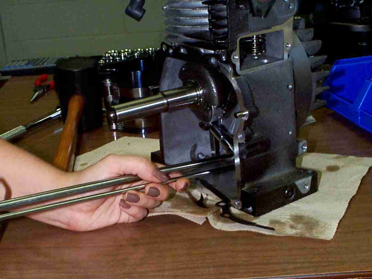
After spending a total of 4 5 hours adjusting caps every which way removing caps and bearings trying a test fit no bearings crank journal reassemble etc. When installing no tang bearings they must be centered on the rod and cap bearing bore surfaces. The bearing housing and pin bores are measured with a sunnen ag 300 precision gauge or dial bore gauge for size and out of round. Bending twisting and alignment of connecting rod problems related to connecting rod problems in internal combustion engines ic engine after any rectification or reconditioning has been carried out on connecting rod they should be checked for correct alignment before they are re erected in the engine.
The proper condition of a connecting rod is fairly straightforward. Standard procedure to repair connecting rod big end bore stretch is to. In addition it must be measured at the rod journal bearing housing tunnel bore the piston pin tunnel bore and the center to center distance. The large or small end centerline slightly offset from the centerline of the rod beam.
The rod must be straight center to center rod length must meet design specs the pin bore and big end bore must be perfectly round each bore must be sized appropriately for wrist pin and crank rod pin fit and oil clearance and the rod must be free. Once the connecting rods are straightened bored and honed then you can put the proper size bushing in the small end which is a very important step according to some engine builders. Hone to oversize c. Machine back to standard size d fit undersize bearing.
Bending twisting and alignment of connecting rod points. A connecting rod alignment fixture is used to check all of the following except a. We ll be seeing more and more of these applications from the oem side. The connecting rod is considered like both ends hinged for buckling about x axis and both ends fixed for buckling about y axis.
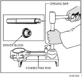
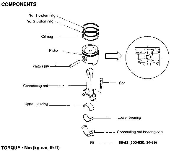
Bore to oversize b. Connecting rod or y axis is a neutral axis. Reassemble the piston and connecting rod by sliding the piston pin back into place in the piston if necessary use the wooden dowel and mallet to tap the piston pin back into place ensure the letters that were previously marked on the connecting rod are matched and aligned with the letters on the bottom side of the piston as shown. It should closely fit the rod to prevent nicks and scratches.
Use the bar to bend the rod in small increments. The connecting rod must be measured for alignment. According to rankine formulae.

Dimensional Inspection Part Two
Chapter 28

Inspecting Measuring The Pistons Pins Connecting Rods Goodson Tools Supplies
Engine Mode Codes Ppt Download

Chevrolet Kent Moore Engine Piston Connecting Rod Tools Wanted Gm Chevrolet Buick Cadillac Oldsmobile Pontiac Kent Moore Carter Carburetor Borroughs 701 588 4541
Inspection

Auxillary Engine Connecting Rod Checks Youtube

Connecting Rod Twist And Bend Gage Youtube
Hercules Jxd Connecting Rod Modification

Inspecting Connecting Rods Youtube

Mbe 4000 Section 1 18 Piston Piston Ring And Connecting Rod Detroit Diesel Engine Troubleshooting
Series 60 Section 1 21 Piston And Connecting Rod Assembly Detroit Diesel Engine Troubleshooting

Connecting Rod Selection Help From Scat Crankshafts
Toyota Supra Jza80 2jz Gte Engine Cylinder Block Inspection

Connecting Rod Honing Basics Goodson Tools Supplies

Piston And Connecting Rod Installation 4ja1
Kia Optima Reassembly Repair Procedures Cylinder Block Engine Mechanical System Kia Optima Tf 2011 2020 Service Manual

Practical Machinist Largest Manufacturing Technology Forum On The Web
Https Encrypted Tbn0 Gstatic Com Images Q Tbn 3aand9gcqkxekypumevofhgbmrtmpybdwslyjfddh8inbwci4s3quh06a9 Usqp Cau
Piston And Connecting Rod Assembly
John Deere Xuv 620i Gator Utility Vehicle Service Manual Tm 1736

Aluminum Connecting Rods Pauter

Hydraulic Cylinder Wikipedia

Ford Y Block Engines Machining And Parts Selection Diy Ford

K Motor Isuzu Manual De Servicio

How To Check Crankshaft End Play
Connecting Rod Clip Bore Hi Tech Compressor Pump Products Inc

2 Stroke Cylinder Installation Procedures And Concerns With The Piston Rings Youtube

Back To Basics Reconditioning Connecting Rods Engine Builder Magazine

Connecting Rod Connecting Rod Repair

How To Make A Connecting Rod Balancing Jig Youtube
7 3 Idi Connecting Rod And Bearing Work Idi Online
Kubota L245dt L2350 L2550 Engine Service And Maintenance
Professional Kohler Engine Rebuilding Buildups And Modifications
Does It Matter Arc Racing

Piston Replacement 2 Connecting Rod Piston Rings Mahle Youtube
Kubota D1503

Connecting Rods An Overview Sciencedirect Topics
Timing Belt Installation Procedures On 1994 2001 Acura B18 Series Engines Engine Builder Magazine
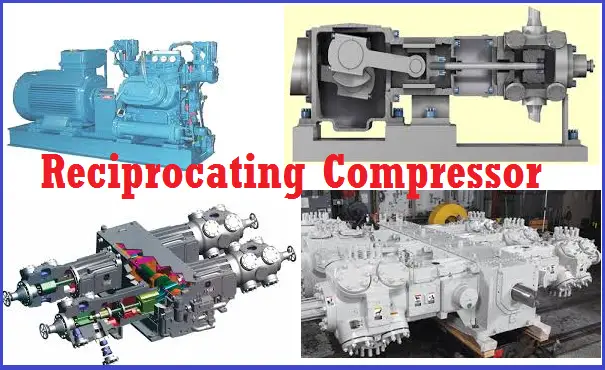
Overview Of Reciprocating Compressors What Is Piping All About Piping Engineering
Https Www Brightonk12 Com Site Handlers Filedownload Ashx Moduleinstanceid 1133 Dataid 5905 Filename Pistonmechanismtutorial Rewite Pdf

How To Build Racing Engines Connecting Rods Guide

